Using GNSS receivers as active control provided accuracy and accelerated the construction schedule for one of Boston’s tallest residential buildings.
Rising 685 feet into the sky, Millennium Tower Boston is the city’s third-tallest building and one of the tallest residential structures, eclipsed only by The Winthrop Center scheduled to be completed in March 2022. At the time of the tower’s construction, it was also one of the biggest professional challenges Eric Dionisio, lead engineer for subcontractor S&F Concrete, had ever faced. “It was taller and bigger than any cast-in-place building we ever worked on,” he says. “Just working from the basement level up to level six was one of our most demanding projects ever.” In fact, on April 26, 2014, the 6,000 cubic yards of concrete delivered for the foundation slab was the highest volume pour in Boston history for a private development.
Dionisio was responsible, among other things, for the building’s vertical alignment during construction. The sheer height of the building made that a daunting task, as it ruled out conventional methods for maintaining plumb, like transferring ground control (or control from nearby buildings) via total stations. There was also significant time pressure. “We were the first crew on a newly poured floor,” he explains. “No one else could get started until we set a new zero point on that floor, set control, and completed all layout.”
“I wondered if performance would degrade as we started doing work several stories above the base station. But by the time we reached 32 stories above the base station, we hadn’t observed any issues with accuracy.”
– Eric Dionisio
Excavation-related delays set the construction schedule back eight weeks by the time the third floor was completed. “Fortunately, by floor six, we’d made all that up, and we stayed ahead of schedule from that point.”
Dionisio attributes much of that gain to more efficient establishment of vertical alignment and improved surveying and layout procedures.
New Solutions for New Challenges
For this project, S&F chose the GNSS-based vertical alignment system developed by Leica Geosystems for use on the Burj Khalifa (world’s tallest building) and One World Trade Center (tallest in the Western Hemisphere). It depends on GNSS receivers placed on the exterior protective screen and used as active control points that move up as floors are completed. On the Millennium Tower, three Leica GR25 receivers were used—two on the north wall and one on the south wall.
A fourth GR25, used as a base station, was placed permanently on the roof of a nearby 10-story building, renovated and owned by Millennium Partners. This receiver continually referenced the Massachusetts Continuously Operating Reference Station Real-Time Network (MaCORS), operated by MassDOT. “My working receivers continually referenced our own permanent base station, which in turn was tied to MaCORS,” Dionisio explains. “That provided plenty of redundancy and position checks, and really raised my confidence in the system.”
The base station location was chosen mainly for convenience, and Dionisio was initially concerned about its suitability. “It was only at 10 stories and was quite near the Tower, so I wondered if performance would degrade as we started doing work several stories above the base station,” he says. “But by the time we reached 32 stories above the base station, we hadn’t observed any issues with accuracy.” S&F Concrete bought several more receivers for use on other projects, such as Boston’s Lovejoy Wharf, Emerson College and The Point, and will have access to its own dedicated base station indefinitely.
The working receivers were mounted on brackets on the perimeter protection system, essentially a 40-foot screen and safety structure that surrounded the building under construction. It extended one floor up and two floors down and was moved up as floors were poured and finished. The receivers were equipped with 360 degree prisms, vertically aligned with receiver antennas, so that the continually updated positions of the receivers could be used by optical total stations and scanners for layout and as-builts. This arrangement was used to position forms after crane lifts, and to ensure that all internal structure was placed properly relative to external walls.
S&F Concrete’s contract included all layout and alignment of the new structure, which was checked every 5th floor by a third party surveyor hired by the general contractor, Suffolk Construction Co. This check was performed with a vertical collimator to basically look straight down through sleeved holes in floor slabs. “We were within three-eighths of an inch every time,” Dionisio says.
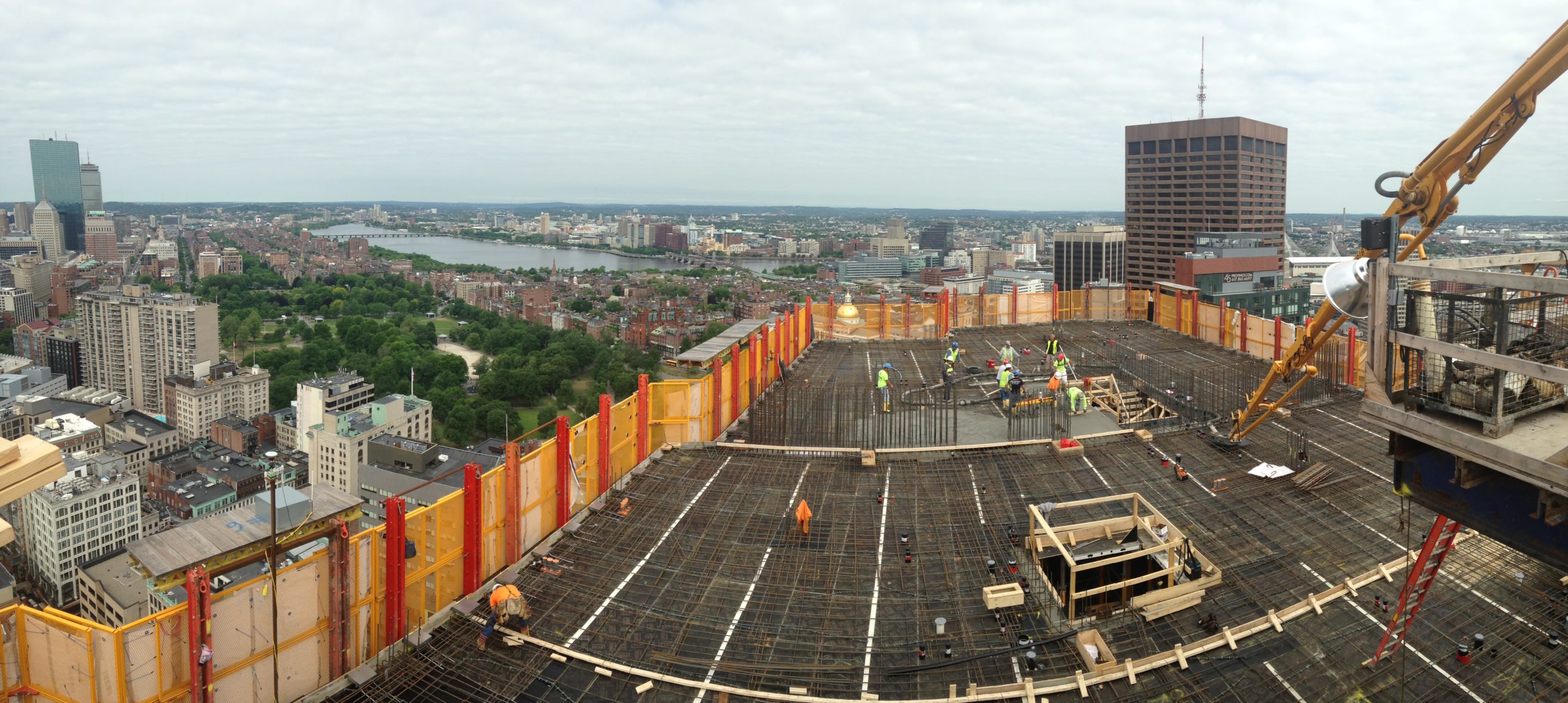
Without GNSS, Dionisio would have likely used optical total stations to transfer ground control, floor by floor. It’s a traditional method that has been in use for decades, but it has at least two weaknesses when applied to taller buildings. One is that as the building grows taller, the geometry of optical surveying becomes unfavorable. It’s more difficult to check backsights accurately as sight lines are impeded and instruments have to be pointed nearly straight down. And, thanks to trigonometry, the increasingly acute angles between the working floor and control points on the ground (or nearby buildings) inevitably expand error ellipses.
For business purposes, a less obvious but more important factor is speed; sighting several backsights from multiple positions, and performing and checking resection calculations, is unavoidably tedious, especially since, as mentioned, every other subcontractor (and S&F themselves) on the construction site is waiting for surveyors to finish control so they can perform their layout and install their work on the floor.
On some tall buildings, vertical alignment is maintained with sightings through slab penetrations, and early skyscrapers sometimes used elevator shafts to hang heavy plumb bobs on wire. This system achieves adequate accuracy and was used on Millennium Tower as a check, but its effect on modern tall-building workflows is unworkable. “If we were dependent for position on the sleeved holes we place for a vertical laser, we would have had to wait until the new slab was nearly cured before we could start work on a floor,” Dionisio explains. “And frankly, that would never happen—crews want to get in there as quickly as possible, and it’s hard to hold them off. As surveyors, we don’t want to be the cause of delays.”
State of the Art Workflow
“Before we decided on the Leica system, I thought we’d be using a vertical laser that sights through holes placed in new concrete floors,” Dionisio explains. “But that method has a lot of negatives. For one thing, accuracy is only good up to 250 feet or so, and if you set the zero point during a period of sway, accuracy is degraded in a way that affects all subsequent construction.”
And placing holes in slabs is also a problem. They’re set during the pour, which meant that setting the new zero point on a new floor would require a slab that had cured to a point where it could be worked. Actually, at least two points would have had to be sleeved up per floor in order to perform resections. That could hold up work for hours and create headaches for surveyors. “As the trades move onto a floor, their stock gets placed wherever it’s needed, and things get crowded. Just keeping vertical sight lines open is a challenge. And, we would have been responsible for closing up holes. Instead, that was someone else’s problem.”
The surveying crew could move onto a new slab as soon as it could be walked on and set the zero point and critical layout lines before other trades moved in. Since they didn’t have to work around other crews and material stockpiles, the work went faster and was more accurate.
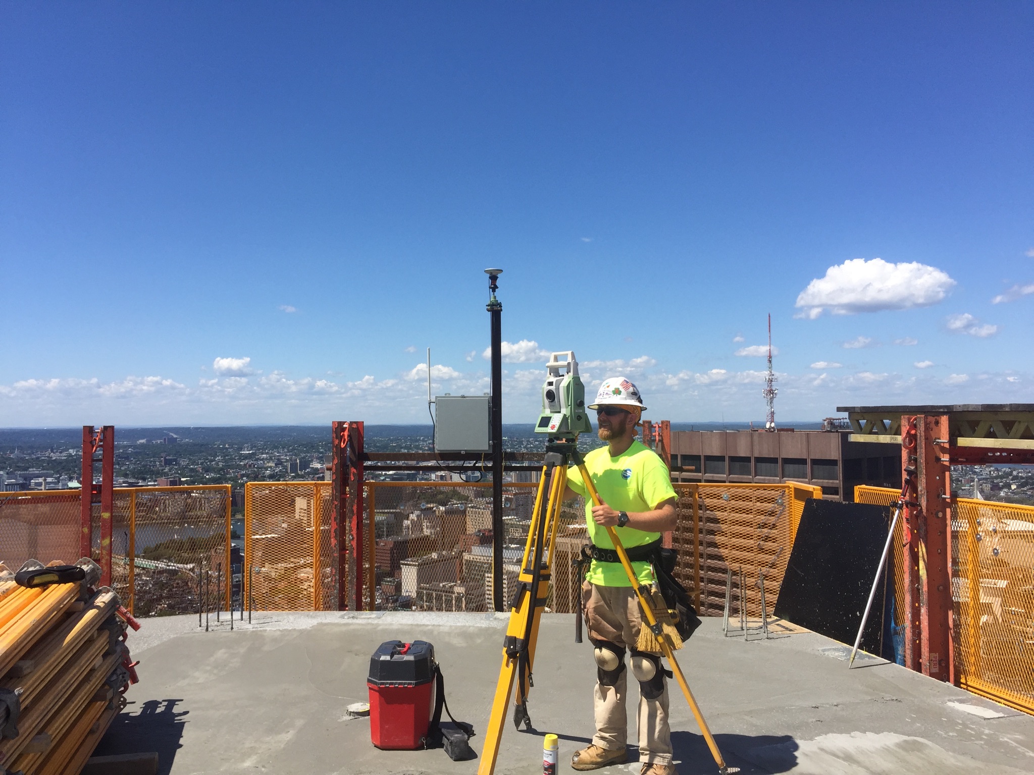
Coordinates were provided in real-time. “I thought at first I’d be doing a lot of static work and post-processing with the GNSS receivers,” Dionisio says. “But we quickly learned that wasn’t necessary.” Dionisio set GeoMoS to compute an average position of the three building-mounted receivers every 15 minutes, and to average those readings every hour. “So to check for sway, I could compare the coordinates we were using to any past set. Over time, I realized that sway was not an issue on this building and that we could always use the real-time coordinates we had for resections. I observed very subtle movement, but nothing that affected our work or overall building tolerances.”
Leica Geosystems’ vertical alignment systems are adapted to the particulars of each construction site. Transforming the GNSS geolocated coordinates to the local coordinate system has traditionally been a little complex, requiring the GNSS feed to go into the Leica Spider software suite first for translation, and then to GeoMoS. However, an innovation was introduced on this project that greatly simplified the work. Smart receivers were used that performed the translation themselves, and the translated coordinates were passed directly to GeoMoS. This approach held down costs, simplified training, and sped up the workflow.
One reason this approach worked on the Millennium Tower was cellular communication. Verizon cards were installed in the working receivers so the receivers could talk with each other and with the base station. Options used on other projects include WiFi and radio, but “WiFi didn’t work here because the density of the reinforcing steel and concrete in this building killed connections,” Dionisio said.
Although cellular connections have height restrictions (cell tower systems are oriented downward, toward people, so signals are weak over a certain height), Millennium Tower, at 650 vertical feet, was under that limit.
For his part, Dionisio was pleased with the performance of the vertical alignment system. “Because it was a new process for me, I didn’t really know what to expect when we started work on the tower,” Dionisio says. “I certainly expected more building movement than we observed, and I thought that using GNSS would require static work and post-processing, especially as we got to higher floors. But that wasn’t the case.”
In fact, Dionisio says that 12 to 14 satellites were in view at all times of day, that vertical alignment was always within a few hundredths of a foot, and that good quality coordinates were always readily available.
The workflow improvements on this project alone justified the investment in new equipment, to the point that S&F Concrete bought another three GR25 receivers for use on other projects while construction of the tower was still under way.
To talk to one of our experts and learn more about solutions for surveying and monitoring, please contact us.
Lead image: Jp16103 – Own work, CC BY-SA 3.0, https://commons.wikimedia.org/w/index.php?curid=44839138

