Knowing how to simulate a network to test performance as well as how to balance accuracy and redundancy will help you optimize your network design.
When designing a monitoring network, it is useful to be able to simulate the network and test performance before we go to the trouble of actually installing sensors and establishing points or prisms to be monitored. After simulation and testing, we arrive at a much more accurate and efficient design, which will require less adjustment of physical sensors and monitored points after installation.
Simulating a network requires input of three key sets of data:
1) Geometry—the 2D location of sensors (terrestrial or GNSS), prisms, and monitored points. For simulation purposes, these coordinates can be approximate.
2) Topology—the observations you will be taking from each sensor, including vertical angles and distances. You can think of this as adding 3D information to your 2D network schematic and, again, this data can be approximate.
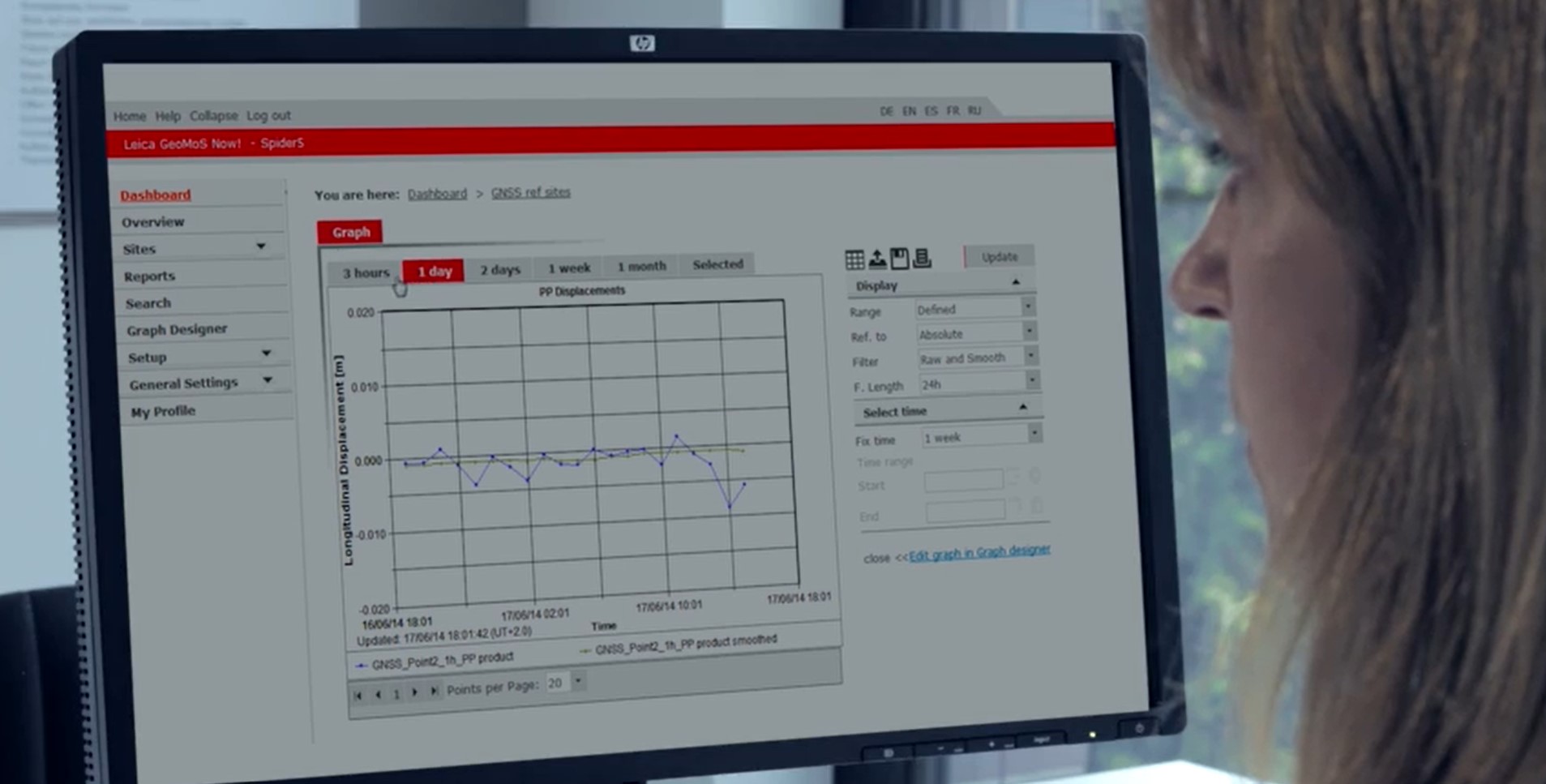
3) Sensor Accuracy—This is a key factor when establishing likely error ellipses in your network. You can start with manufacturer specs for the instruments you are using (in Leica GeoMoS Adjustment software, you can select predefined instrument types), and if you believe that there are factors that may affect sensor accuracy, such as a thick glass enclosure surrounding a total station, you can estimate the magnitude of that effect.
 “After simulation and testing, we arrive at a much more accurate and efficient design, which will require less adjustment of physical sensors and monitored points after installation.”
– Craig Hewes, PLS
Much of this data will be approximate for simulation purposes—but of course, the better the approximation, the better the simulation. In most situations, you will likely have at least preliminary base mapping to work with, and you may want to perform additional surveying prior to simulation in order to get better data on possible sensor positions. In some cases, as some sensor and/or reference point locations are ruled out, the simulation itself may prompt additional preliminary surveying.
With the simulation created, you can “run” it, and take a look (via graphic views and detailed numerical charts) at likely error ellipses at points of interest—this may well lead to changes in your design, and further simulation.
Balancing Accuracy and Redundancy
To make judgements about the quality of the network design, the two components accuracy and redundancy have to be balanced for the required project’s needs.
The redundancy is related to the control, whereas the accuracy is related to the ability to determine network values with a certain precision. Practically speaking, the accuracy of the selected instrument and the network geometry is important.
When we talk about balancing accuracy and redundancy, we are talking about reconciling an ideal network with the real-world network we are actually able to create, within the physical and financial constraints that apply. For example, in an ideal network all total station observations would be at or near 90º from long backsights, so we have the best possible network geometry, and all instruments used would be the most accurate available, regardless of cost (and we’d use a lot of them).
But we do have constraints. So, we have to use our simulations to see if we are achieving, within those constraints, sufficient accuracy for project purposes. There are two main strategies for improving accuracy within given constraints: increasing point redundancy and increasing sensor accuracy.
Increasing point redundancy can be as simple and cheap as adding more precisely located reference (control) points to the network. For example, if site topography seemed to rule out very long backsights due to expense, a simulation may reveal that establishing a tower to raise a prism is, in fact, a cost-effective way of improving total network accuracy. Or, it may be worth the trouble to locate additional prisms on the monitored asset—a bridge or earth dam, say.
Increasing sensor accuracy is usually expensive. A more precise total station may be needed, or a higher quality GNSS receiver, or an additional sensor of any type. But sometimes, improving sensor location, or giving it better reference points, will help.
One technique I recommend can sound like a trick, but in fact is more like a useful best practice in most large networks with multiple sensors. The technique is to place a prism at a sensor location in the same vertical axis as the sensor. When this is done, only a height offset is needed, and this greatly improves least squares adjustment calculations since the height differences are managed (automatically) in the network via instrument heights and reflector heights. This would usually be a 360º mini-prism, mounted on custom handles available as options for most receivers and total stations, or beneath tribrachs on custom bolts, or on separate tribrachs or mounts under the sensor.
Another best practice technique is to distinguish between, in a given set of points being collected from a total station, the stable reference points and the potentially unstable points being monitored. In a given epoch (monitoring cycle) the stable points should be measured twice—before and after the points being monitored. This usefully increases redundancy, and also provides a check against unpredictable factors, such as a total station settling in ice on a warm day.
And, as in most cases involving data, more is better. Extended data in a single epoch has the advantage that chances of a complete network computation failure, singularly caused by too many missing observations (e.g. obstructions, etc.), is reduced. And, more data acts almost identically as a smoothing of results. For example, a spontaneous movement appears in smaller steps, but the tendency would be significant. Another method to increase the amount of data per set is to use longer computation intervals (by comparing points over longer periods of time in which change can happen), but then the network adjustment computation frequency is reduced.
With this basic approach, you should be able to set up and make use of a network simulation and, based on the simulation, identify ways to improve network design so that greater accuracy is achieved.
About the Author:
 Craig S. Hewes, PLS, is a licensed land surveyor who is experienced in supertall building construction and asset monitoring. For nearly 15 years, Craig served as Leica Geosystems' director of monitoring for the Eastern US and Canada. In his current role as Leica Geosystems' senior strategic account manager, Craig helps surveying and engineering organizations achieve new levels of success through a strategic partnership approach to technology adoption.
To talk to one of our experts and learn more about solutions for surveying and monitoring, please contact us.

